Here's the standard in question, happy reading, good luck
The NF S 56-200 Standard
Caravans and Motorhomes (Camper Vans)
French standard approved by decision of the Director General of AFNOR on June 20, 1987 to take effect on July 20, 1987.
As of the date of publication of this standard, it is in partial accordance with ongoing ISO work, with certain liquefied petroleum gas installation conditions being specific.
This standard aims to reduce the risks of fire and asphyxiation in caravans and motorhomes by establishing minimum requirements regarding emergency exits, ventilation, risk zones surrounding household appliances, as well as the installation and use of liquefied petroleum gas and liquid fuels.
International Technical Thesaurus: accident prevention, fire protection, caravan, safety rules, requirements, emergency exits, ventilation, gas installation, liquid fuel installation.
Prevention of fire and asphyxiation hazards.
1 PURPOSE
This standard specifies the main safety requirements that caravans must meet in order to prevent fire hazards, fire spread in the event of fire, as well as asphyxiation hazards.
Note: electrical installation is covered by a separate standard (NF S 56-201).
2 SCOPE OF APPLICATION
This standard applies to caravans, rigid foldable caravans, motorhomes (1) and converted vans (1) unless otherwise specified.
3 DEFINITIONS
3.1 Caravan. A habitable vehicle, towed, which meets the requirements for construction and use of road vehicles.
3.2 Foldable caravan. A caravan of rigid construction, or otherwise, whose structural dimensions can be reduced.
3.3 Motorhome (1). A motor vehicle equipped, occasionally or permanently, with a habitable unit, or a habitable motor vehicle, which meets the requirements for construction and use of road vehicles.
Note: the vehicle is either adapted from a series-produced vehicle or designed and built on an existing chassis with or without a driver's cab. The habitable area may be fixed or removable.
3.4 Converted van (1). A motor vehicle whose equipment and layout allow for habitation.
4 REFERENCES
· NF 0 35-351. Flame heaters operating on commercial butane. Appliances not connected to a flue or special evacuation system.
· NF D 35-352. Mobile heaters with catalytic combustion operating on commercial butane. Appliances not connected to a flue or special evacuation system.
· NF D 36-101. Flexible hoses with elastomer base, 6mm internal diameter, for household appliances using butane or propane.
· NF G 07-184. Textiles - Fire behavior - Classification method according to surface burned.
· NF P 92-507. Fire safety - Buildings - Construction and interior finishing materials - Classification according to reaction to fire.
5 EMERGENCY EXITS
5.1 For caravans and foldable caravans, each habitable compartment, separated otherwise than by a non-lockable curtain, must be equipped with an emergency exit giving direct access outside the caravan.
Sanitary compartments equipped in the rooms defined in Chapter 3 must be equipped with an emergency exit when evacuation requires passing in front of a risk zone (heating appliance, cooking appliance), except when their own door is less than 1.50m, clear of any obstruction, from the caravan door. Distance measured from handle to handle, doors being closed.
5.2 The openings constituting emergency exits (1) must have the following minimum areas and dimensions:
· For caravans and foldable caravans, and sanitary compartments of motorhomes and converted vans: minimum clear opening of 0.20m and 0.45m in their smallest dimensions.
· For children's bedrooms separated with stacked beds: minimum clear opening of 0.20m and 0.35m in their smallest dimensions. Additionally, the lateral anti-fall protection of the upper bunk must provide a minimum passage of 0.45m to facilitate evacuation.
The inner free edge of openings constituting emergency exits must not be at a height greater than 0.95m from the floor.
5.3 For caravans and foldable caravans, window or emergency exit panels (1) opening by projection must be able to open to at least 70° and must remain open by automatic locking. Similarly, window or emergency exit panels opening by vertical sliding must be able to remain open by automatic locking.
5.4 Exterior doors must not open inward. The closure must be such that it must be impossible to close the door without being able to open it immediately from inside.
5.5 The opening mechanism of interior doors must be able to be operated from both sides; in the case of a lever handle, opening must be achieved by pressing downward; furthermore, in the case of a door with a lock, an emergency unlocking system must be provided from the other side.
(1) For motorhomes and converted vans, refer to texts applicable under road traffic regulations in which other dimensions are prescribed for emergency exits.
6 VENTILATION - AERATION
6.1 In each room, air vents (1) must be provided with a total minimum free section that cannot be blocked (2) of 20cm² in the upper part and a minimum total free section (2) of 10cm² in the lower part.
6.2 Any room intended to house one or more appliances using non-sealed circuit gaseous fuels (3) must have one or more openings allowing fresh air intake with a total free section of at least 100cm² in addition to the aeration section provided in 6.1
These openings, which may be distributed at several points in the room, must be arranged in the lower part, with the lower part of the opening located at most 10cm from the floor.
6.3 An evacuation opening (1) with a minimum free section of 150cm² (4) must be provided above the kitchen area.
6.4 The external openings of ducts serving to evacuate combustion products must be located at least 0.50m from a fresh air intake opening.
If the room contains one or more appliances not connected to a combustion gas evacuation duct, it must have one or more openings allowing evacuation of combustion products (4) with a total free section of at least 150cm² in addition to the aeration section (1) provided in 6.1, arranged in the upper part of the room at most 10cm from the ceiling and at least 0.50m from any fresh air intake in the room.
6.5 Adjustment and protection of openings
Aeration and combustion gas evacuation openings may be fitted with devices allowing the section to be varied according to atmospheric conditions.
In this case, the section remaining free must be at least 50cm² in closed position and at least 150cm² in open position for fresh air intakes, at least 100cm² in closed position and at least 200cm² in open position for openings allowing evacuation of combustion gases.
Openings must be arranged and designed to prevent the entry of rain and dust and not be a nuisance to occupants. These openings must be easily cleanable.
(1) To ensure proper air ventilation transit, openings located inside a chest or cabinet must be arranged so they cannot be accidentally blocked by objects that may be stored there.
7 REQUIREMENTS FOR HEATING, COOKING AND OTHER APPLIANCES.
7.1 General Requirements
7.1.1 All appliances must be fixed and in no case must be mounted on doors or installed in front of emergency exits.
7.1.2 Appliances must be installed according to the methods recommended by the appliance manufacturer in the instruction manual which must be provided by the manufacturer.
7.2 Heating Appliances
7.2.1 Requirements common to all appliances
7.2.1.1 Only appliances designed to prevent the temperature of their directly accessible parts from exceeding 150°C at the appliance's rated power must be installed.
Verification of this temperature must be performed at an ambient temperature between 20°C and 30°C and after a 2-hour period.
However, if the appliances comply with an approved standard or specification or are subject to approval and meet the above condition, this verification need not be performed.
Furthermore, appliances must be equipped with a manual or automatic temperature regulation system or a device limiting heating.
7.2.1.2 Manufacturers must take all measures to ensure that the temperature of walls and furniture and the ambient air near appliances does not exceed 65°C when they operate at a regime allowing maintenance of a temperature of 20°C ± 5°C inside the room (for an outdoor temperature of 5 to 10°C), temperature measured 1m above the ground at the center of the room after a 2-hour period.
The same applies to walls or furniture near evacuation pipes, forced air ducts or the passage through the pavilion or room wall.
In the case of forced air installation not using an automatic heating shutdown device in case of air propulsion system failure, a second temperature reading must be performed after 2 hours of air propulsion device shutdown.
7.2.1.3 Manufacturers must take all necessary precautions to ensure that appliance fixing and evacuation duct centering remain satisfactory when the vehicle is in motion.
7.2.2 Gas heating appliances
Gas heating appliances must be of the sealed circuit type.
They must be connected to a device for evacuating combustion products outside, made of a material in the M0 fire reaction category (appliances discharging combustion products into the room are prohibited).
Note: For auxiliary gas heating appliances, refer to paragraph 8.2.2.
7.2.3 Heating appliances operating on liquid fuels
Heating appliances operating on liquid fuel must be connected to a device for evacuating combustion products outside, made of a material in the M0 fire reaction category. They must also comply with the requirements of 9.2.3.
Note: Auxiliary heating appliances operating on liquid fuel are not permitted.
(2) This requirement does not apply to air-conditioned rooms.
(3) An appliance is said to be "non-sealed circuit" when the air necessary for combustion is taken directly from the room where it is installed. It is "sealed circuit" when the combustion circuit (air intake, combustion chamber, burnt gas outlet) does not communicate at any point with the air of the room in which this appliance is installed.
(4) The "roof light" may serve this function, if, when closed, one or more openings of at least 100 cm² total section remain.
7.2.4 Electrical appliances
Only appliances complying with the requirements of Decree 75-848 of August 26, 1975 as amended and standards enacted for application of Article 6 of the aforementioned Decree may be used.
7.3 Cooking Appliances
7.3.1 General Provisions
7.3.1.1 When the appliance is placed on a piece of furniture whose top consists of a non-metallic surface, this surface must be covered with a material in the M1 fire reaction category (1).
7.3.1.2 When the cooking appliance housing includes a cover, it must be made of material in the M3 fire reaction category (1). This cover, once closed, must not come into contact with the burner grilles.
7.3.2 Flame-visible appliances
7.3.2.1 All walls or elements located at a distance of less than 30cm from the appliance burners, distance measured from the point of flame emission, must be made of or covered or protected with material in the M0 fire reaction category.
In the case of a metal sheet, the minimum thickness must be 0.3 mm.
7.3.2.2 When curtains are located near the appliance, they must belong to Class B as defined in standard NF G 07-184. Maintenance in this class must be ensured after washing.
7.3.3 Other appliances
The requirements for installation of these appliances are the same as those for heating appliances with regard to wall temperatures. Measurement will be performed after 1 hour of operation at maximum setting.
7.4 Gas hot water production appliances
Hot water production appliances must be installed in compliance with the same wall temperature requirements as those provided for heating appliances. Measurement will be performed after 10 minutes of operation at maximum setting intended for use.
Hot water production appliances must be connected to a device for evacuating combustion products outside.
However, in rooms with a volume of at least 15m³, hot water production appliances, called instantaneous water heaters, whose useful power is less than or equal to 8.7kw (125mth), are exempt from the obligation of connection to a flue, provided that:
they are equipped with a safety device cutting off gas supply when the carbon monoxide content of the atmosphere in the room where the water heater is installed reaches 100vpm (0.01%).
they meet the tests in sealed chamber and ventilated room defined by the Order of May 3, 1978 on safety devices for gas instantaneous water heaters with power less than or equal to 8.7kw and not connected to a combustion product evacuation duct.
(7) According to standard NF P 92-507, materials that can claim the NF fire reaction mark are strongly recommended.
7.5 Gas refrigerator
Refrigerators must be installed in compliance with the same wall temperature requirements as those provided for heating appliances. Measurement will be performed after 2 hours of operation at maximum setting.
Refrigerators must be arranged so that their combustion products are evacuated outside (for example, by means of an opening fitted with a protective grid and located directly at the rear of the appliance).
Furthermore, fresh air intake must be arranged near the burner to ensure proper operation.
7.6 Gas lighting fixtures
Fixtures must be installed in compliance with the same wall temperature requirements as those provided for heating appliances. Measurement will be performed after 1 hour of operation at maximum setting.
8 GAS INSTALLATIONS
This chapter applies to liquefied hydrocarbon installations (commercial butane and commercial propane). It does not apply to installations serving vehicle propulsion).
8.1 General Rules applicable to manufacturers and installers
8.1.1 Appliance Supply
· Appliances may be supplied with commercial butane or commercial propane.
· Propane containers with capacity greater than 6.5l must be placed outside the room.
· If the room is specially designed for winter use, appliances must be supplied with propane (1).
· A clearly visible sign specifying the nature of the gas used (BUTANE or PROPANE) and the supply pressure of the appliances (28 mbar or 37mbar for example) must be fixed near the bottle station.
8.1.2 Installation of bottle stations
8.1.2.1 Outside or inside the room
Containers must be secured to prevent them from moving during room transfers. The securing system must allow for quick removal without the aid of tools.
8.1.2.2 Inside the room
Spaces reserved for bottles must be designed such that:
· bottles can be easily placed in the designated space without being tilted.
· robinet operation and disassembly are easy.
· room ventilation openings cannot be blocked.
If bottles are placed in an enclosed housing, it must be ventilated by openings in the upper and lower parts with a minimum section of 50 cm² each.
(7) In cold weather, the vapor pressure of butane is too low to ensure proper appliance operation.
8.1.2.3 Outside the room
Bottles may be installed either in the open air or inside a shelter, recessed or not into the room.
If they are in the open air, the location provided for their installation must be located more than 0.50 m from doors and windows of the room or any aeration opening.
If they are in a shelter, it must be designed such that bottle and robinet operation is convenient.
The shelter must be ventilated by openings in the upper and lower parts with a minimum section of 50 cm² each and must not contain any apparatus capable of producing flames, incandescence or sparks, or any opening communicating with the inside of the room. Very low voltage cables passing through this shelter must be protected or arranged so as not to be damaged by bottle manipulations. The opening(s) located in the upper part of the chest must be at most 10cm below the robinet of the container(s) (5).
Ventilation openings must be located more than 0.50 m from doors and opening windows of the room or any aeration opening thereof. This distance is measured according to the actual path of the vapor from the point of vapor emission.
8.1.3 Equipment and connection of stations
Bottles supplying appliances must be equipped with accessories and safety devices adapted to each type of supply.
Based on the number of appliances used, the location and composition of the supply station, it must necessarily include the equipment indicated in Annex A.
In the case of multiple appliance supply, the station must provide the flow and pressure necessary for the normal operation of all appliances.
Valves and pressure reduction devices located outside must be protected from impacts and weather (for example, protected by a cover).
8.1.4 Supply pipework
8.1.4.1 Usable pipework
Fixed supply pipework for appliances must be metallic (steel, copper or brass exclusively) and provide all guarantees of tightness, resistance to mechanical, physical, chemical or electrolytic actions.
The various elements of pipework must be assembled by methods guaranteeing good tightness and good resistance.
The use of soft soldering in particular (fusion temperature of filler metal less than 450°C) is prohibited.
Flexible connecting hoses (flexible loops) are intended to connect either a bottle to an accessory, or a bottle accessory to fixed pipework.
Flexible hoses may only be used to individually connect fixed pipework or a container accessory to an appliance other than a fixed heating appliance or hot water production appliance.
The end of the fixed pipework or accessory to which the flexible connection hose to appliances is connected must be placed inside the room and arranged such that the length of the flexible hose does not exceed 1.50m and does not hinder room occupants.
5.1.4.2 Installation of pipework
The entire pipework system must be installed by experienced personnel. Pipework must be properly fixed (approximately one fixing per 0.50 m for copper and 1 m for steel) and protected wherever it risks undergoing impacts or friction and, in particular, must be mechanically protected when fixed under the floor.
It may be placed under skirting boards, casings or double-wall partitions, provided that access is possible, if necessary by simple disassembly of these skirting boards, casings or walls and the volume thus created is in direct communication with the atmosphere at both ends. Pipework arranged inside these skirting boards, casings or partitions must not include any screwed element or fitting.
Pipework must not be in direct contact with metal parts of the room structure and its support or in contact with metal pipes (hot or cold water, etc.).
The minimum space between gas pipework and accessories and electrical conduits must be:
· 3 cm in parallel runs.
· 1cm at crossings.
This distance is increased to 0.10 m between gas pipework and accessories and the vehicle exhaust pipe.
Where pipework enters the room, the annular space between the wall and the pipe must be sealed by means of a flexible joint ensuring mechanical protection of the tube.
If pipework enters the room through the floor, it must also be protected by a rigid sheath extending the floor on the upper part by at least 5 cm. This protective sheath must have an internal diameter at least 1cm greater than the external diameter of the pipe it protects. The inner ends must be deburred so as not to damage the pipework.
In the case where pipework is awaiting a future appliance, its end (even if including a robinet or accessory) must be sealed by means of a threaded, sealed cap.
8.1.4.3 Pipework tightness check
After installation and after any modification of the installation (1), fixed butane and propane pipework must, under the responsibility of the manufacturer or installer, undergo a tightness test performed with air or preferably with an inert gas (nitrogen).
The test may be performed using the service gas (butane or propane). If performed with air the control robinet or pressure reducer-interrupter with incorporated robinet must remain accessible when the supplied appliance is in place.
The control robinet may be that of the container if it is placed directly nearby and supplies only a single appliance.
When the fixed pipework connection to the appliance is made by flexible hose, the control robinet or pressure reducer-interrupter with incorporated robinet must be:
· arranged such that the condition of the flexible hose can be verified.
· arranged such that the flexible hose fitting is easy.
· fixed such that its repeated operation does not risk damaging the pipework.
The test of pipework from the butane or propane container(s) to the final pressure reduction, is performed under a pressure of 3 bars (controlled by a metal pressure gauge with 0.1 bar precision). The control robinets arranged upstream of the appliances being in the closed position.
For pipework from final pressure reduction to appliances, tightness tests are performed at double the service pressure, with a minimum of 150 mbar (controlled by liquid column manometer).
When test pressure is stabilized, no leaks must be detected in the following 5 minutes.
Tests are considered satisfactory if investigation of all joints, fittings and welds by means of a foaming solution reveals no leaks and if gas can pass normally through all parts of the pipework.
The search for gas leaks using flame is strictly prohibited.
8.1.6 Verification of appliance operation
The installer must ensure that appliances installed by them in accordance with the requirements of paragraph 7 are suitable for the pressure and gas used. Verification of the operation of appliances must also be performed.
8.2 General Instructions applicable to users
8.2.1 Installation use instructions
The operating pressures of appliances being different depending on whether butane or propane is used (butane 28 and 112 mbar, propane 37 and 148 mbar), an installation cannot be supplied indifferently with one or the other of these two gases without the necessary modifications being made.
Containers located inside or outside a mobile room must be kept closed outside periods of use and during its movements. The same applies to non-connected containers, even presumed empty.
It is forbidden to obstruct aeration devices provided in upper and lower parts for air renewal in the room or to use fixed pipework as earth for electrical or radio installations.
8.2.2 Auxiliary heating appliances
These appliances must be secured. Any auxiliary heating appliance must comply with standards NF D 35-351 and NF D 35-352 or a specification concerning it and ensuring equivalent safety (1).
8.2.3 Container installation
Containers supplying the installation must be installed at locations provided for this purpose.
They must rest stably and be properly secured to prevent tipping or overturning. The securing system must allow for quick container removal without the aid of any tool.
Butane or propane containers must not be placed near or under radiation from a heat source likely to raise their temperature above 50°C.
Propane containers, connected or not, with capacity greater than 6.5l must be placed outside the room.
(1) The nominal heat output of these appliances is limited to 4.65 kw (4 th/h). They are equipped with a safety device interrupting gas supply in case of:
· extinction or failure to ignite.
· elevation of carbon monoxide content of the atmosphere above 100 vpm (0.01 %).
Connection of pipework to appliances
Fixed pipework must be fitted, for each appliance, with an independent shut-off robinet located upstream of it in immediate proximity or, if the connection is made by flexible hose, immediately upstream of it, or the pressure reducer.
(7) An intervention not affecting the system's tightness, such as fitting a cap after removing an appliance for example, is not considered a modification of the installation.
8.2.4 Reserve containers
Regardless of installation mode, only one non-connected butane container with capacity greater than 10 liters or one non-connected propane container with capacity less than or equal to 6.5 liters may be stored in the room.
Any transfer of butane or propane from one container to another is prohibited.
8.2.5 Container connection
Connection and disconnection of butane or propane containers must be done in the absence of flames or sparks after verification of closure of the robnets of these containers. If containers are on the drawbar of a mobile room the vehicle engine must be stopped.
Before connection or disconnection of container(s) located outside, in shelter or not, it is verified that any opening into the room and located less than 1m away is well closed.
The presence and good condition of the tightness joint must be verified before connecting a container to the installation.
8.2.6 Flexible hoses
Flexible hoses must be replaced as soon as their condition requires and in any case before the expiry date.
Only flexible hoses complying with standard NF-GAZ Butane-propane NF D 38-101(1) may be used.
Their length must be sufficient to avoid any tension but also as short as possible and in any case never exceed 1.5 m.
Flexible hoses must be securely fastened at both ends and arranged to be neither reached by flames nor damaged by combustion gases, hot appliance parts or product overflow during cooking.
If necessary, they must be fixed, without constraint, at several points along their length to prevent damage from swinging caused by room movement. Their replacement must however remain easy and they must remain accessible over their entire length.
It is forbidden to use a flexible hose to connect a bottle station located outside to pipework or an appliance installed inside the room.
8.2.7 Appliance adjustment
It is forbidden to modify appliance adjustment as well as the bore of injectors and burners or to modify their shape, outside cases provided in the installation instructions supplied with these appliances.
8.2.8 Installation verification
The installation must be verified every year or at least before each return to service.
This verification will particularly focus on the condition of pipes (flexible and rigid), the securing of containers and connections to appliances.
When there is suspicion of leakage, the use of appliances or other objects capable of producing flames, incandescence or sparks (lighter, gas igniter, cigarette, etc.) is forbidden.
To search for leaks, appropriate means must be used such as foaming liquid for example. The search for leaks using flame is strictly prohibited.
(1) Hoses complying with this standard bear the following indication: NF- GAZ Butane-Propane followed by the expiry date.
9 LIQUID FUEL INSTALLATION
This chapter does not apply to installations serving vehicle propulsion.
9.1 Definition
For the purposes of this standard, liquid fuel means a fuel with a flash point greater than 50°C (domestic fuel oil for example).
Note: Certain kerosenes which may have a low flash point (equal to 38°C) are excluded from use in habitable vehicles due to the danger their storage may represent. All the more so, the same applies to gasoline. Diesel fuel intended for vehicle propulsion is also excluded.
9.2 General Requirements
9.2.1 Installation must be performed according to appliance manufacturers' instructions while respecting Chapter 7 requirements.
9.2.2 All appliances must be easily accessible to permit checks, maintenance, repair and replacement.
9.2.3 Steps must be taken to ensure that in case of leakage, fuel cannot spread either inside or outside the room, whether or not the tank is an integral part of the appliance.
9.3 Tanks
9.3.1 The tank, with capacity necessarily less than 50 l, must include an easily accessible shut-off robinet.
9.3.2 When the tank is not an integral part of the appliance, filling and draining must be done from outside the caravan.
In this case, the tank must be installed in a compartment including, in addition to an opening to allow fuel drainage, ventilation openings in the upper and lower parts with a minimum section of 50 cm² each. Furthermore, the compartment must not include any apparatus capable of producing flames, incandescence or sparks, or any opening communicating with the inside of the room. Very low voltage cables passing through this compartment must be protected or arranged so as not to be damaged by tank manipulations.
9.4 Pipework installation
9.4.1 Pipework must be made of steel or copper, according to best practice rules applicable to the category of material used, and provide all guarantees of tightness, resistance to mechanical, physical, chemical or electrolytic actions.
9.4.2 Connections between different pipework elements must be of the flat joint type and be made with components resistant to liquid fuels. Soft soldering connections (fusion temperature of filler metal less than 450°C) are prohibited.
9.4.3 Pipework must be properly fixed and mechanically protected, either by its location or by sheaths or any other means.
10 NOTICES AND CERTIFICATES
10.1 Notices
A notice, written in French recalling the main safety measures to be taken to avoid fire and asphyxiation hazards, must be affixed to the inside of a cabinet door, or in any visible location if the room has no cabinet.
This notice must mention the following recommendations:
· do not leave heating appliances and gas-supplied appliances operating during travel. Close the bottle robnets.
· do not obstruct aeration devices provided in the upper and lower parts of walls for air renewal.
· replace flexible connection hoses as soon as their condition requires and in any case before the expiry date.
· only use fire extinguishers of the multi-purpose powder type, bearing the national conformity mark to standards (NF-MIH)(1).
When no space is originally provided for the later installation of a heating appliance, the notice must also include the following information:
· the use of a mobile heating appliance presents fire or asphyxiation hazards.
· this room is not equipped with a designated space for a heating appliance.
· any auxiliary heating appliance must be properly secured.
Furthermore, notices written in French relating to operation instructions for each appliance that is part of the room must be provided by the manufacturer.
10.2 Certificates
Upon taking possession of a room as defined in Chapter 3 of this standard, a certificate of compliance will be given to the user.
(7) French standard - Approved fire equipment.
* ********************************************************************
* *
ANNEX A
This annex is an integral part of the standard
EQUIPMENT AND CONNECTION OF A LIQUEFIED HYDROCARBON STATION
(Application of paragraph 8.1.3)
The installation may include one or more fixed (1) butane or propane stations depending on the number of appliances used and the gas flow required for their operation.
Each station must include at least the following elements mounted between the container(s) (bottles) and the appliance(s) (heating, hot water, cooking, refrigeration, lighting).
A.1 Butane station
A.1.1 Supply of a single appliance by a single container placed inside the room: a 28 or 112 mbar pressure reducer. a flexible connection hose to the appliance.
A.1.2 Supply of two appliances by a single container placed inside the room: a 28 or 112 mbar pressure reducer. a flexible loop or connection hose to fixed pipework. fixed pipework. a shut-off robinet arranged on the fixed pipework near each appliance. a rigid tube or connection hose to appliances.
A.1.3 Supply of one or two appliances by a single container placed outside the room.
The provisions of A.1.2 apply, however: the pressure reducer is replaced by a pre-reducer placed on the container or fixed pipework outside the room. shut-off robnets are replaced by safety pressure reducer-interrupters at 28 or 112 mbar with incorporated robinet, arranged upstream of each appliance, or by a single pressure reducer-interrupter provided that a shut-off robinet is placed near each appliance.
Pressure reducer-interrupters or shut-off robnets must be placed inside the room in an easily accessible location.
A.1.4 Supply of multiple appliances by two containers in automatic alternation placed inside the room.
The provisions of A.1.2 apply however: an automatic switcher must be placed between the two loops or the two connection hoses to the containers, and the pressure reducer connected to the fixed pipework.
A.1.5 Supply of multiple appliances by two containers in automatic alternation placed outside the room: a loop or flexible connection hose connecting each container to the automatic switcher. an automatic switcher pre-reducer.
fixed pipework. a pressure reducer-interrupter upstream of each appliance or a single pressure reducer-interrupter provided that a shut-off robinet is placed near each appliance.
Pressure reducer-interrupters or robnets must be placed inside the room in an easily accessible location.
(7) A station is called a butane or propane container, or several containers connected together, allowing supply at the desired pressure to one or more appliances.
A.2 Propane station
A.2.1 Station located inside the room
In this case, each container (whose capacity is limited to 6.5 l) can only supply a single appliance.
The provisions of A.1.1 then apply. The pressure reducer used being necessarily of the propane 37 or 148 mbar type.
A.2.2 Single container station located outside the room:
a fixed regulation pre-reducer at 1.5 bar.
a pressure limiter at 1.75 bar.
a loop or flexible connection hose to fixed pipework.
fixed pipework.
a pressure reducer-interrupter with incorporated robinet at 37 or 148 mbar, arranged upstream of each appliance or a single pressure reducer-interrupter provided that a shut-off robinet is placed near each appliance.
Pressure reducer-interrupters or robnets must be placed inside the room in an easily accessible location.
A2.3 Two container station in automatic alternation located outside the room.
Provisions A2.2 apply. However the pre-reducer is replaced by an automatic switcher and its connection to the containers is provided by loops or flexible or rigid connection hoses."



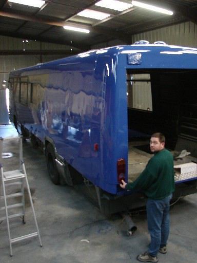




 😏
Okay I'm out😏
😏
Okay I'm out😏







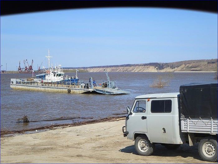
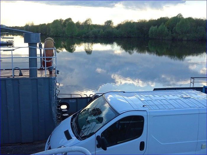
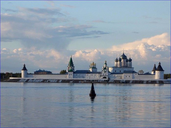
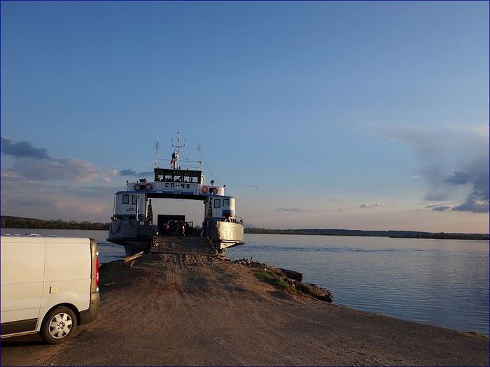
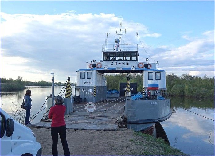 After an hour of waiting, a worker arrives and tells us they *will* cross the Volga tonight,
but the exit ramp at Makaryevo isn’t accessible for our vehicle.
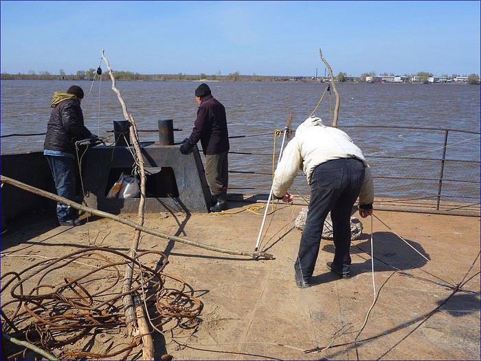
The captain joins him, and seeing our disappointed faces, they confer, discuss,
and load some planks to raise the ramp!
After an hour of waiting, a worker arrives and tells us they *will* cross the Volga tonight,
but the exit ramp at Makaryevo isn’t accessible for our vehicle.
The captain joins him, and seeing our disappointed faces, they confer, discuss,
and load some planks to raise the ramp!